Looking for answers?
Type your questions here
Type your questions here
- Home
- Data Sheets
- Encoder MDT

MDT
Encoder Data Transceiver
Standard, MAX, and LoRaWAN Systems
Product Overview
The Tehama Encoder MDT has a true encoder interface that directly reads the meter face value of encoded meters to transmit an absolute reading toward the DCAP / Gateway. It auto-detects the data format between Sensus meters, Sensus-compatible meters (Master-Meter, Badger, etc.) and Neptune meters. A separate model (suffix –G or –GG) is available for GWF ECO meters.
Our Encoder MDT is offered in three radio technologies—our original Standard Range, the MAX Range, and now LoRaWAN. Standard is our first-generation system, which we continue to support. MAX is based on LoRa but uses Repeaters. LoRaWAN follows the international IoT radio standard. All MDTs are powered by two inexpensive, field-replaceable AA batteries.
Units ship in single-input versions for individual meters or dual-input versions for two co-located meters (e.g., hot/cold water).
Other variations include:
- Submersible version for pit/outdoor installation (see Submersible Data Sheet)
- Integrated Remote Display, California-approved (see Display MDT Data Sheet)
Specifications
| Input | -E : Sensus UI-1203 or Neptune (auto-detect) -G : GWF AllRead UNICOcoder® interface |
| MDT Data Storage | No local storage |
| Data Resolution | One-hour interval |
| Radio | 902 – 928 MHz; FCC / IC certified • Standard: open-field ≈ 1 mile • MAX: open-field ≈ 10 miles |
| LED | Indicates power and network status: • Green = good link • Amber = OK link • Red / flashing = poor link or syncing |
| Operating Environment | -20 to 145 °F, ≤ 90 % RH (non-condensing) |
| Power | Two replaceable AA batteries (≤ 8 yrs typical) |
| Dimensions | 4.3" × 2.2" × 1.2" |
| Warranty | Five years (batteries excluded). See warranty page. |
Continual product enhancements may cause specifications to change without notice.
*Actual range may vary depending on installation location and topography.
Models
| Standard System | Model # | Description |
|---|---|---|
| Single Encoder MDT | TW-160B-E | Single encoded input, one-hour interval |
| Dual Encoder MDT | TW-160B-EE | Dual encoded input, one-hour interval |
| MAX System | Model # | Description |
| Single Encoder MDT | TW-170B-E | Single encoded input, one-hour interval |
| Dual Encoder MDT | TW-170B-EE | Dual encoded input, one-hour interval |
| LoRaWAN System | Model # | Description |
| Single Encoder MDT | TW-180B-E | Single encoded input, one-hour interval |
| Dual Encoder MDT | TW-180B-EE | Dual encoded input, one-hour interval |
Other combinations and sensor inputs are available by special order (e.g., dual input with Pulse + Encoder -EP). Please contact Tehama for details.
Note: Standard, MAX, and LoRaWAN products are NOT compatible; each MDT must pair with its corresponding Repeaters, Gateways, and DCAPs.
Refer to AN-119 for additional details.
MDT Configuration
All MDTs ship with a preset configuration; factors such as count and units are set in our software.
New MDTs are shipped powered off. Power on using the hidden button under the Tehama Wireless logo; the LED provides feedback.
Turn ON or Off:
- Press and hold until the LED blips off (~3 s), then release.
- Encoder MDTs wake automatically once daily if a meter is detected.
Power-up LED flashing (1 s rate):
- Listening for a DCAP, Gateway, or Repeaters; flash rate doubles when a beacon is heard.
- LED goes solid for 10 s once connected, or turns off after 60 s if no connection.
Check status (tap the button):
- Two flashes → unit OFF
- One flash → unit asleep (out of range)
- LED solid 10 s → unit connected (Green = robust, Orange = OK, Red = poor)
Reset:
Press and hold until the power-up flashing sequence starts (~12-15 s). A reset can also be done by briefly removing a battery.
MDT to Meter Wiring
TW-160/170/180 B-E & B-G Encoder (Sensus / GWF color order)

TW-160/170/180 B-EE & B-GG Dual Encoder (Neptune color order)
Important: Encoder Primary / Secondary positions are reversed from Pulse units; the Primary Encoder connector occupies the terminal labeled “Secondary Pulse” on some boards.
Use the Sensus wiring order for Sensus and compatible meters. Dual Encoder MDTs can read two Sensus meters, two Neptune meters, or one of each.

Meter connectors may be swapped; wiring order remains correct.
Recommended System Installation Steps
Warning: radio devices should be placed at least 8 in / 20 cm from people to minimize RF exposure.
1. Power the DCAP, then position Repeaters outward, using the LED (solid 10 s) to confirm range.
2. After backbone placement, install MDTs; add Repeaters where MDTs cannot connect.
3. Open-field range is ≈ 10 miles for MAX / LoRaWAN and ≈ 1 mile for Standard; construction materials and terrain reduce range.
The CIT software provides detailed signal-quality metrics during placement.
Wiring Instructions
Do not mount directly on metal or inside a metal enclosure—RF performance degrades.
Recommended placement
- Mount on a nearby wall away from metal piping.
- Best performance on wallboard.
- Use the keyhole slot with a #6 drywall screw.
- Case halves separate to tighten screw if needed.
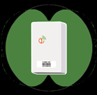
- Radio pattern is slightly attenuated along the MDT’s long axis.

